Products
Toys
Schools
Industry and Universities
ft Design Studio
Service
fischerTiP
Search for...
Home
Schools
Learning material
Gears
Learning material
Everything around the topic
of gearboxes
Didactic material accompanying the products Class Set Gear and STEM Gear Tech
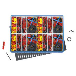
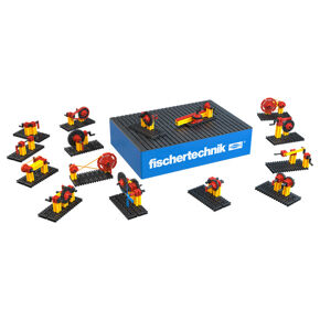
More info about the product Class Set Gears
To the product page
Ready-made lesson plans Class Set Gears
Download lesson plans
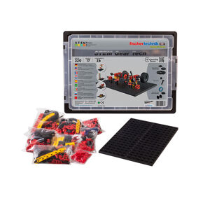
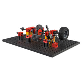
More info about the product STEM Gear Tech
To the product page
Ready-made lesson plans STEM Gear Tech
Download lesson plans
Topic Introduction
Historie
Basic principles (primary level)
Fundamentals (Secondary level I+II)
Weiterführende Informationen
Construction manual Class Set Gears
Construction manual STEM Gear Tech
cd-84f54cbff4-6zvpz